
TM 5-4220-211-12&P
15A430/18A430 DISASSEMBLY/ASSEMBLY
i.
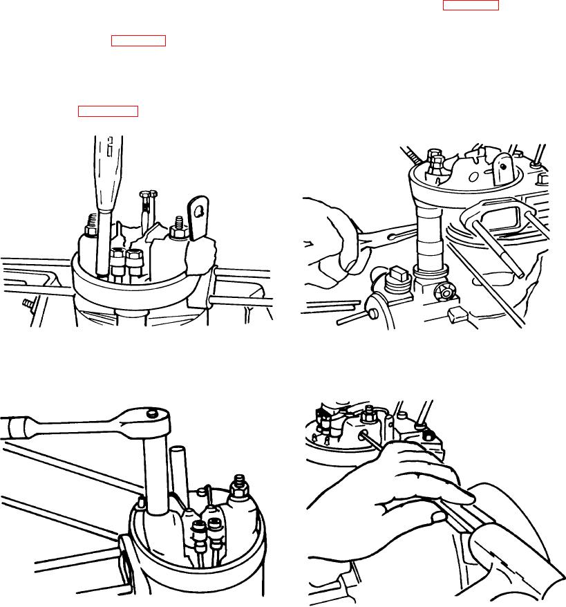
Cylinder Head. With an 8mm nut driver, remove the push rod tube retaining spring. (Figure A-8)
(1) Remove the bolt holding the two cylinder head shields together using a screwdriver and needle nose
pliers. (Figure A-9)
(2) Beginning with the two injector side nuts, loosen the 4 cylinder head nuts with a 13mm deep well socket.
(Figure A-10.)
(3) Knock out the rocker arm shaft with a drift pin and hammer. Pull out the rocker arms and push rods.
Figure A-8. Cylinder Head
Figure A-9. Bolt Holding Two Cylinder Head
Figure A-11. Rocker Arm Shaft
Figure A- 10. Two Injector Side Nuts
A-7