
TM 5-4220-211-12&P
15A430/18A430 DISASSEMBLY/ASSEMBLY
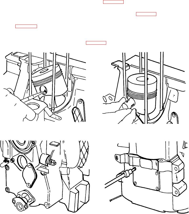
m. Piston. Slowly rotate the flywheel until the piston reaches the top of its stroke. With a needle nose pliers,
remove the piston pin retainer on the governor side of the engine. (Figure A-16.)
(1) Pull out the piston pin. If the pin does not come out easily, insert a hook (such as a bent coathanger)
through the center of the pin and pull while gently rocking the piston. (Figure A-17.)
n. Oil Filter Screen. Before removing the connecting rod, drain the engine oil. Remove the oil filter screen
assembly,. (Figure A-18.)
o. Connecting Rod. Turn the engine onto its flywheel side. Remove the crankcase inspection cover by
removing the six allen screws with a 4mm allen wrench. If these screws are very tight, tapping on them with a hammer
and drift pin or flat-faced punch may help loosen them. (Figure A-19).
Figure A-17. Piston Pin
Figure A-16. Piston
Figure A-18. Oil Filter Screen
Figure A-19. Connecting Rod
A-9