
TM 5-4220-211-12&P
15A430/18A430 DISASSEMBLY/ASSEMBLY
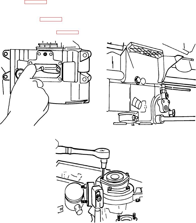
(1) Using a 13mm socket, remove the two connecting rod hex nuts. Tap on the connecting rod cap with a
hammer handle, if necessary, to loosen and remove it. Pull and remove it. Pull out the connecting rod.
p. Injection Pump. With the 13mm socket, remove both the injection pump hex nuts. Pull the injection pump
from the gear cover. Leaving the injection pump gasket and shims on the gear cover, reinstall the hex nuts and
lockwasher on their studs. (Figure A-21.)
q. Crank Handle Guide. Remove the two crank handle guide screws with a 5mm allen head wrench. Pull off
the guide, o-ring and o-ring retainer. (Figure A-22.)
Figure A-20. Rod Hex Nuts
Figure A-21. Injection Pump
Figure A-22. Crank Handle Guide
A-10