TM 5-4220-231-14&P
(2)
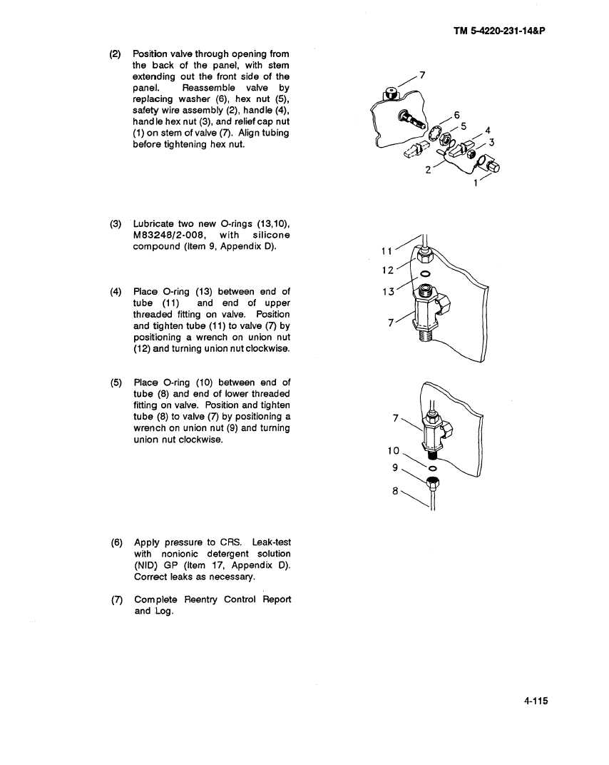
Position valve through opening from
the back of the panel, with stem
extending
out the front side of the
7
panel.
Reassemble
valve
by
replacing
washer
(6), hex nut (5),
safety wire assembly
(2), handle (4),
6
handle
hex nut (3), and relief cap nut
5
(1) on stem of valve (7). Align tubing
4
before tightening
hex nut.
(3)
Lubricate two new O-rings (13,10),
M83248/2-008,
with
silicone
compound
(Item 9, Appendix
D).
11
12
(4)
Place O-ring (13) between
end of
13
tube
(11)
and
end
of
upper
threaded
fitting on valve.
Position
and tighten tube (11) to valve (7) by
7
positioning
a wrench
on union nut
(12) and turning union nut clockwise.
(5)
Place
O-ring (10) between
end of
tube (8) and end of lower threaded
fitting on valve.
Position and tighten
tube (8) to valve (7) by positioning
a
7
wrench
on union nut (9) and turning
union nut clockwise.
10
9
(6)
Apply pressure
to CRS.
Leak-test
with
nonionic
detergent
solution
(NID) GP (Item 17, Appendix
D).
Correct
leaks as necessary.
(7)
Complete
Reentry
Control
Report
and Log.
3
4-115


