TM 54220-231-14&P
(3)
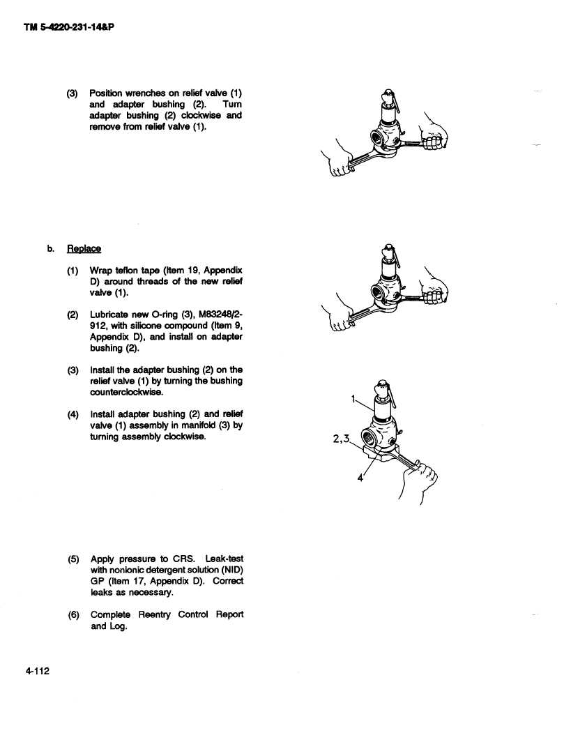
Position wrenches on relief valve (1)
and
adapter
bushing
(2).
Turn
adapter
bushing
(2) clockwise
and
remove from relief valve (1).
b.
Replace
(1)
Wrap teflon tape (Item 19, Appendix
D) around threads
of the now relief
valve (1).
(2)
Lubricate
new O-ring (3), M83248/2-
912, with silicone compound
(Item 9,
Appendix
D), and install on adapter
bushing (2).
(3)
Install the adapter
bushing (2) on the
relief valve (1) by turning the bushing
counterclockwise.
(4)
Install adapter
bushing
(2) and relief
valve (1) assembly
in manifold (3) by
turning assembly
clockwise.
2,3
4
(5)
Apply pressure
to CRS.
Leak-test
with nonionic
detergent
solution
(NID)
GP
(Item 17, Appendix
D).
Correct
leaks
as necessary.
@4
(6)
Complete
Reentry
Control
Report
and
Log.
4-112