TM 5-4220-211-12&P
15A430/18A430 DISASSEMBLY/ASSEMBLY
j.
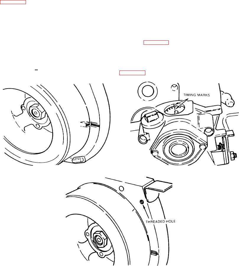
Gear Cover. To install the gear cover, first bring the crankshaft to TDC1 (top dead center). This is (lone by
aligning the flywheel timing mark with the TDC mark stamped on the crankcase at the :3 o'clock position.
(1) Next, line up) the timing mark on the cam gear with the mark on the gear cover. This mark is visible on
the inside ridge of the compression release mounting flange.
(2) Install the gear cover (remember to replace the gaskets) onto the crankcase being careful not to move
the cam gear. After the cover is installed, check the timing by aligning the cam gear with the timing mark
on the gear cover and checking the timing mark on the flywheel. If the crankcase and flywheel timing
marks are within 1/4" of lining up, the timing is correct. (Figure A-48).
(3) Occasionally, however, the governor will tighten onto the crankshaft in a position that makes it difficult to
install the gear cover. If this happens, use the following procedure to install the cover.
a
Turn the flywheel until its timing mark aligns with the threaded hole in the crankcase at
approximately the 1 o'clock position. (Figure A-49.)
Figure A-47. Gear Cover
Figure A-48. Timing Marks
Figure A-49. Threaded Hole
A-18

