
TM 5-4220-211-12&P
15A430/18A430 DISASSEMBLY/ASSEMBLY
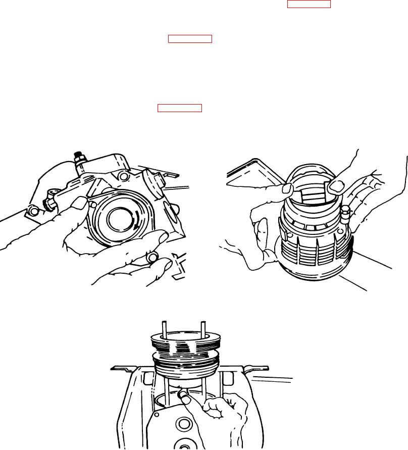
(2) Finally, replace the oil seal and crank handle guide. Do not push the guide straight onto the gear cover.
Instead, while holding the camshaft gear with one hand, use a light twisting motion until the guide seats
itself. Tighten the two guide screws with a 6mm allen head wrench. (Figure A-41.)
g. Piston. Fit the piston ring compressor to the piston. Lay the cylinder down on the bench so the bottom of the
cylinder is facing up. Install the piston from the bottom of the cylinder. Never tap on the top of the piston. Do not push the
piston in so far that the piston pin bore is covered. (Figure A-42.)
(1) Slide the piston and cylinder over the studs, making sure the crescent shaped grooves in the cylinder
fins face the governor side of the engine. Align the piston and connecting rod bores. Push the wrist pin
into the piston and through the connecting rod. Replace the wrist pin retaining ring using a snap ring
pliers.
(2) Slide the cylinder down until it seats firmly on the engine block. On 18A430 engines only, install a new
copper cylinder head gasket. Slide the cylinder head down onto the cylinder. Replace the flat washers
and flange nuts on the studs. (Figure A-43.)
h. Governor. Make sure the governor threads are free of oil and grease. Apply a couple of drops of Lock-Tite
to the threads. Screw the governor on hand tight in a counterclockwise direction (left-hand thread). Torque the
Figure A-41. Replacing Oil Seal and Crank Handle
Figure A-42. Piston
Guide
Figure A-43. Piston and Cylinder
A-16