TM 5-4220-211-12&P
15A430/18A430 DISASSEMBLY/ASSEMBLY
governor according to engine specifications. The ,weights must be spread apart slightly so that the socket will completely
cover the governor screw head: Install the governor pin. NOTE: Before torquing the governor, place a block of wood
through the crankcase and flywheel to keep the flywheel from turning. (Figure A-44.)
i.
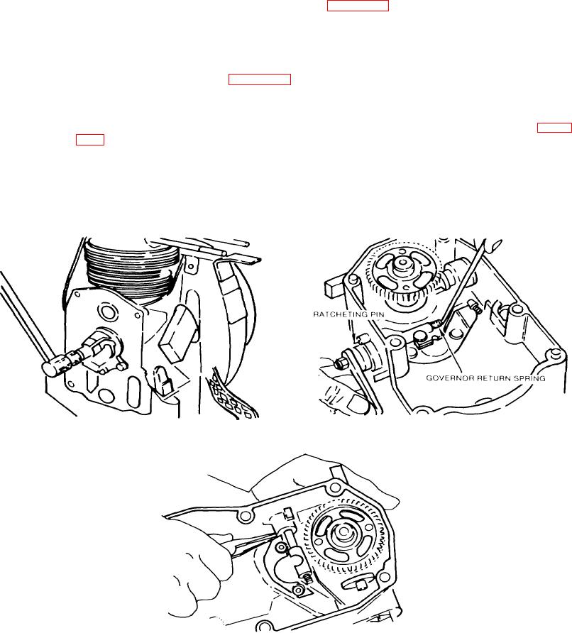
Governor Control. Install a new o-ring on the speed control shaft. Place the speed control lever ratcheting
pin in its hole in the gear cover. Lay the governor lever in the housing and slide the control shaft through the governor arm
about 3, into the housing. Twist the lever downward towards the working surface until the slotted end of the speed control
shaft lines up with the hook on the governor return spring. Make sure the spring is
completely seated in the slotted end of the shaft. (Figure A-45.)
(1) After turning the speed control lever with its end points upward, plush the control shaft into the housing
until the control shaft's retaining ring groove is visible. Push on the retaining ring with your thumb on
screw-driver handle. Hook the large end of the outside return spring across the boss of the pin. (Figure
NOTE
There are three closely spaced notches on the speed control lever racket
plate. Usually the spring should be placed in the middle notch. However,
if there is not enough spring tension to return the lever from its engine
stop position to its idle position, place the spring in the uppermost of the
three notches.
Figure A-45. Governor Control
Figure A-44. Governor
Figure A-46. Speed Control Lever
A-17

