
TM 5-4220-211-12&P
(5)
Rotate crankshaft until second stage piston is at top dead center. Piston should be flush with top of
cylinder. If not, adjustment has to be made with gaskets under cylinder.
(6)
Install second stage valve head. (Ref. para 4-41)
k.
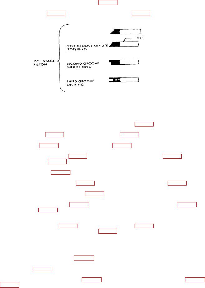
Install first stage piston and piston rings (25, and 26, Fig. D-4).
(1)
Install piston rings (26, Fig. D-4) into ring grooves in piston (25, Fig. D-4) as shown in Figure 4-10.
Figure 4-10. Compressor First Stage Piston Ring Installation.
NOTE
Always install piston rings with the "top" mark toward the top or head of the piston.
(2)
Lubricate the connecting rod, piston and wristpin (28, 25 and 27, Fig. D-4).
(3)
Install one circlip (24, Fig. D-4) into groove in piston. (25, Fig. D-4).
(4)
Position piston (25, Fig. D-4) over connecting rod (28, Fig. D-4).
(5)
Align wristpin bore of piston (25, Fig. D-4) with bearing in connecting rod (28, Fig. D-4). Install wristpin
and circlip (24 and 27, Fig. D-4).
l.
Install first stage cylinder (20, Fig. D-4).
(1)
Install first stage cylinder gasket (23, Fig. D-4) over first stage cylinder studs (30, Fig. D-4).
(2)
Lubricate bore of first stage cylinder (20, Fig. D-4).
(3)
Position first stage cylinder (20, Fig. D-4) over top of first stage stage piston (25, Fig. D-4). Squeeze
piston rings (26, Fig. D-4) with one hand while pressing cylinder over piston with other hand. The
bottom of the cylinder bore is chamfered to assist in ring installation.
(4)
Seat first stage cylinder (20, Fig. D-4) over first stage studs (30, Fig. D-4). Secure first stage cylinder to
crankcase with 4 nuts and washers (21 and 22, Fig. D-4). Tighten nuts to a torque of 18 lb/ft. (25NM).
(5)
Rotate crankshaft until first stage piston is at top dead center. Piston should be flush with top of
cylinder. If not, adjustment has to be made with gaskets under cylinder.
(6)
Install first stage valve head. (Ref. para 4-4K).
m.
Install aftercooler (6, Fig. D-8).
(1) Loose assemble cooler pipe clamp (14, Fig. D-8) with 1 bolt and washer (16, and 15, Fig. D-8) into
cooler bracket (8, Fig. D-8).
4-23