
TM 5-4220-211-12&P
(4)
Install third stage valve head. Ref. para. 4-4m.
h.
Install oil pressure regulator (6, Fig. D-9).
(1)
Install O-ring (12, Fig. D-9) into O-ring groove in third stage upper cylinder as shown in Figure D-9.
(2)
Position oil pressure regulator (6, Fig. D-9) over oil pressure regulator mounting surface on third stage
cylinder (47, Fig. D-4). Align bolt holes in regulator with bolt holes in cylinder. Secure oil pressure
regulator to cylinder with 2 socket head bolts (10, Fig. D-9).
NOTE
Orient regulator to cylinder as shown in Figure D-9.
i.
Install second stage piston and piston rings (39 and 40, Fig. D-4).
(1)
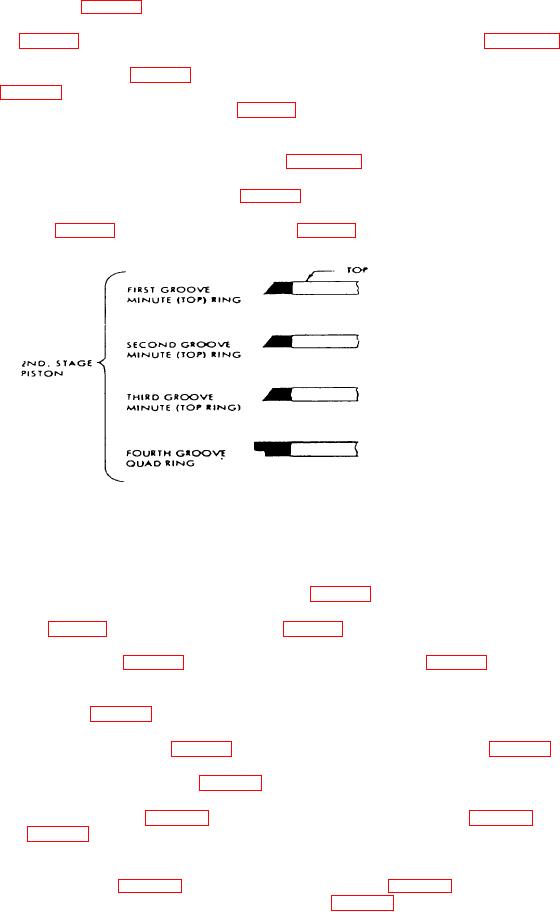
Figure 4-9. Compressor Second Stage Piston Ring Installation.
NOTE
Always install piston rings with the "top" mark toward the top or head of the piston.
(2)
Lubricate connecting rod, piston and wristpin (43, 39 and 41, Fig. D-4).
(3)
Install one circlip (42, Fig. D-4) into groove in piston (39, Fig. D-4).
(4)
Align wristpin bore of piston (39, Fig. D-4) with bearing in connecting rod (43, Fig. D-4). Install wristpin
and circlip (41, and 42, Fig. D4).
j.
Install second stage cylinder (37, Fig. D-4).
(1)
Install second stage cylinder gasket (38, Fig. D-4) over second stage cylinder studs (30, Fig. D-4).
(2)
Lubricate bore of second stage cylinder (37, Fig. D-4).
(3)
Position second stage cylinder (37, Fig. D-4) over top of second stage piston (39, Fig. D-4). Squeeze
piston rings (40, Fig. D-9) with one hand while pressing cylinder over piston with other hand. The
bottom of the cylinder bore is chamfered to assist in ring installation.
(4)
Seat second stage cylinder (37, Fig. D-4) over second stage studs (30, Fig. D-4). Secure second stage
cylinder to crankcase with 4 nuts and washers (21, and 22, Fig. D-4). Tighten nuts to a torque of
181b/ft. (25NM).
4-22