
TM 5-4220-211-12&P
valve (7, Fig. 3-1). The second stage cylinder, second to third stage intercooler and the interstage separator are all
protected from overpressure by the second stage safety valve (8, Fig. 3-1). The compressed air entering the third stage is
compressed to a pressure of about 3260 PSIG (225 BAR). The high pressure air leaving the third stage is cooled to within
about 250 F (140 C) of ambient temperature by the aftercooler (9, Fig. 3-1). It should be noted that the interstage coolers
and the aftercooler are located directly in the air blast from the compressor cooling fan. The cooled compressed air from
the aftercooler enters the final separator (10, Fig. 3-1). The final separator removes the condensed oil and water vapor by
air passing through two separate tubes of different lengths within the separator. The accumulated condensate may be
discharged by the separator drain valve (11, Fig. 3-1). The final safety valve (12, Fig. 3-1) protects the third stage,
aftercooler and final separator from damaging over pressures. The compressed air leaving the final separator flows into
the purifier chamber (14, Fig. 3-1) by way of a check valve (13, Fig. 3-1). The function of the check valve is to prevent a
reverse flow of air from the purifier chamber back into the final separator whenever the condensate in the separator is
drained. Such a reverse flow of air could damage the chemicals in the purifier chamber cartridge. Any accumulated
moisture collecting in the purifier chamber may be drained by the purifier chamber drain valve (15, Fig. 3-1). This drain
valve is also used to relieve any pressure within the purifier chamber so that the chamber may be opened for cartridge
servicing. The pressure maintaining valve (17, Fig. 3-1) prevents passage of air through the chemicals in the purifier
chamber until the pressure rises above about 2000 PSIG (135 BAR). This is done to insure the purifier operates at peak
efficiency. The final pressure gauge (16, Fig. 3-1) and fill pressure gauge (18, Fig. 3-1) indicate the air pressure inside the
purification chamber and the air pressure being delivered to the diver tank block respectively.
3-3.
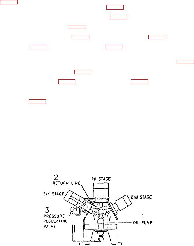
COMPRESSOR LUBRICATION SYSTEM. The compressor is equipped with a positive pressure lubricating oil
system. The oil pump (1, Fig. 3-2) is driven by a cam which is bolted to the end of the crankshaft. The oil pump supplies
oil to a pressure regulating valve (3, Fig. 32) which controls the oil pressure. The pressure regulating valve also controls
the oil flow rate to the third stage cylinder. The surplus oil not required for the third stage is delivered to be base of the
second stage cylinder to provide lubrication for the second stage and the crankshaft. The oil then drains back into the
crankcase sump where it is picked up by the oil pump for recirculation. The first stage is lubricated by an oil vapor drawn
from the crankcase into the intake of the first stage. This high pressure lubrication system insures adequate oil delivery to
all wear points resulting in minimum wear and maximum service life.
NOTE
Use only those oils recommended in Table 2-1. These oils have been
selected for maximum compatibility with this compressor.
Figure 3-2. Compressor Lubricating Oil Flow Diagram
3-2