TM 5-4220-211-12&P
CHAPTER 3
OPERATION
Section I
GENERAL INFORMATION
3-1.
GENERAL. This section describes the basic principles of operation of the air compressor unit and various
methods by which the unit and operating personnel are protected against excessive pressures, contaminated air, etc. This
is followed by a step-by-step procedure for all modes of operation and the safety precautions to be followed to assure safe
and trouble-free operation.
Section II.
PRINCIPLES OF OPERATION
3-2.
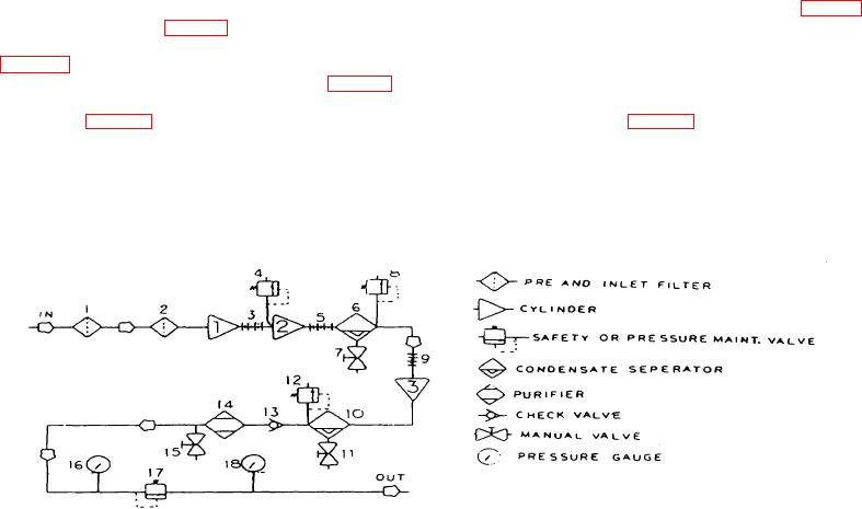
COMPRESSOR AIR FLOW. Air is taken into the first stage of the compressor by way of the prefilter (1, Fig. 3-1)
and the inlet air filter (2, Fig. 3-1). The movement of the piston within the first stage cylinder compresses the incoming air
to about 70 PSIG (4.8 BAR). The air leaving the first stage is substantially cooled by the first to second stage intercooler
(3, Fig. 3-1). Both the first stage cylinder and the first to second stage intercooler are protected from damaging
overpressure by the first stage safety valve (4, Fig. 3-1). The compressed air entering the second stage is compressed to
a pressure of about 550 PSIG (38 BAR). The air leaving the second stage is cooled by the second to third stage
intercooler (5, Fig. 3-1). The cooled compressed air enters the interstage separator (6, Fig. 3-1). Inside the interstage
separator, a sintered metal filter removes any solid contaminants from the air. A series of air directing vanes and baffles
cause the air flowing through the separator to spin. The resulting centrifugal force causes the water vapor and oil vapor
which was condensed by the intercooler to collect on the inside surface of the separator housing and flow down into the
sump area at the bottom of the separator. The accumulated condensate may then be drained by means of the separator
drain
1.
Prefilter
10.
Final Separator
2.
Inlet Air Filter
11.
Separator Drain Valve
3.
Intercooler, lst-2nd Stage
12.
Safety Valve, 3rd Stage, 3260 PSIG (225 BAR'
4.
Safety valve, 1st Stage, 116 PSIG (8 BAR)
13.
Check Valve
5.
Intercooler, 2nd -3rd Stage
14.
Purifier Chamber
6.
Interstage Separator
15.
Purifier Drain Valve
7.
Separator Drain Valve
16.
Discharge Pressure Gauge
8.
Safety Valve, 2nd Stage, 725 PSIG (50 BAR)
17.
Pressure Maintaining Valve
9.
Aftercooler
18.
Fill Pressure Gauge
Figure 3-1. Compressor Air Flow Diagram
3-1

