
TM 54220-211-12&P
valve is to prevent air from passing through the purifier chamber at any pressure below 2000 PSIG. This will insure that
the compressed air remains in contact with the purifier chemicals for long enough time to provide maximum purification
and peak purifier efficiency.
r. Compressor Oil Fill Plug. The compressor oil fill plug (19), which includes the oil level dipstick, is used at a
location to both check the compressor oil level and add oil to the compressor crankcase.
s. Compressor Oil Drain Plug. The compressor oil drain plug (20) provides a discharge point for draining
compressor lubricating oil during an oil change and other maintenance operations.
t.
Compressor Gauges. The compressor gauges (21) are used to give a continuous indication of the
compressor final stage discharge pressure and the pressure entering the fill manifold hose.
u. Fill Hose and Manifold. The fill hose and manifold (22) is used to connect the air discharge from the
pressure maintaining valve to the diver tank block.
1-8.
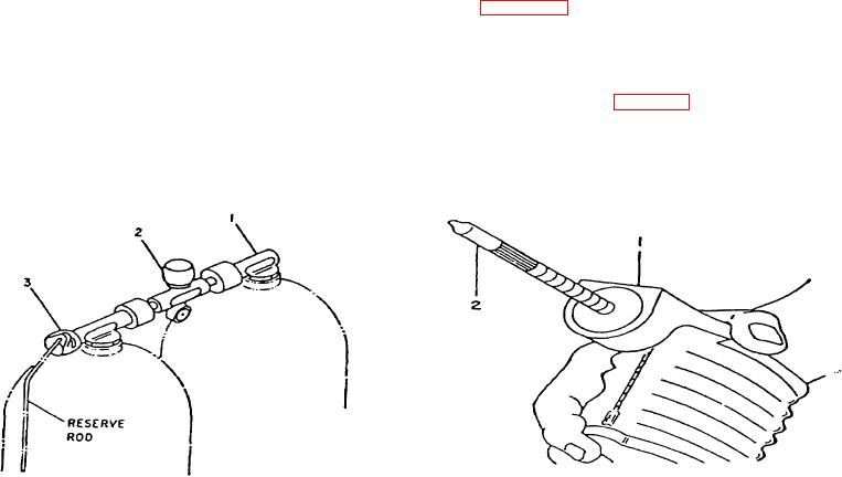
DIVER TANK BLOCK. As stated previously, the tank block consists of twin 80.0 Std. cu. ft. Cylinders joined by a
double constant reserve valve. This double "J" valve (Figure 14) consists of an elbow assembly (1) that connects cylinder
number 1 to the on-off valve (2). The air reserve valve (3) has the dual function of an elbow and a reserve valve. It
connects cylinder number 2 to the shutoff valve (2) through the reserve mechanism and a operates as follows: during the
start of a dive, the reserve valve is in the "up" position. When the pressure in cylinder number 2 falls to approximately 500
psi, this valve will automatically close and create the air breathing reserve in cylinder number 2. When the reserve valve
knob is turned "down" (opened), the air reserve will become activated and be available via the on-off shutoff valve (2).
1-9.
DETECTOR KIT. As stated previously, the pump and test tube (Figure 1-5) constitute a gas detector measuring
instrument. The pump (1) is a bellows type device which is operated by hand and supplies 100 cc with each stroke. With
the proper test tube (2) inserted in the pump head, and the pump operated, a gas sample will be sucked in via the tube.
Depending on the number of pump strokes used and the composition of the test tube, a measurement can then be made
for the gas being tested. Simply read the length of discoloration on the scale of the tube. The numerical value read off is a
measure of the concentration of the gas (e.g., in ppm.) which can then be compared to Table 1-1 to check that it falls
within the limits of breathing air acceptability. Ordinarily, the air should be tested at two locations, entering the prefilter and
discharge from the purifier chamber. In the first
1.
Elbow Assembly for Cylinder No. 1
1.
Pump
2.
Tank(s) Shutoff Valve
2.
Test Tube
3.
Reserve Valve and Elbow for Cylinder No. 2
Figure 1-4. Diver Tank Block Manifold
Figure 1-5. Detector Kit
1-6