TM 5-4220-231-14&P
b.
Replace
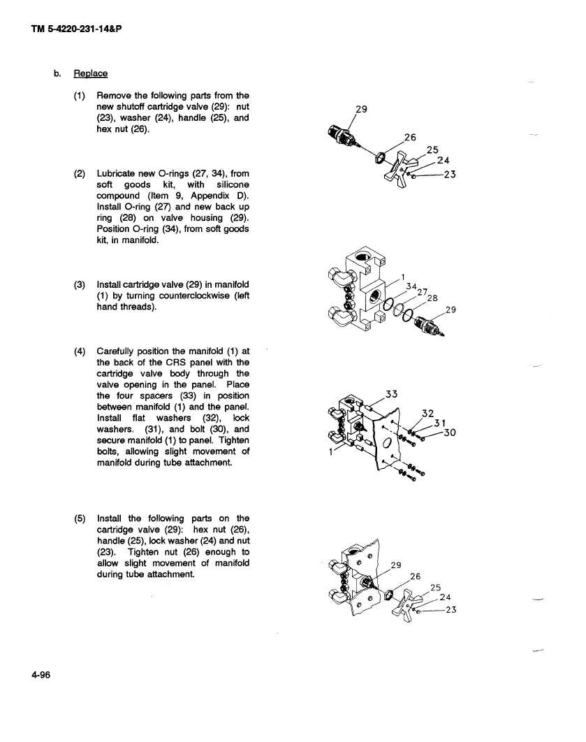
(1)
Remove
the following parts from the
new shutoff cartridge valve (29): nut
29
(23), washer (24), handle (25), and
hex nut (26).
26
25
24
(2)
Lubricate
new O-rings (27, 34), from
23
soft
goods
kit,
with
silicone
compound
(Item 9, Appendix
D).
Install O-ring (27) and new back up
ring (28) on valve housing (29).
Position O-ring (34), from soft goods
kit, in manifold.
(3)
Install cartridge
valve (29) in manifold
34
27
(1) by turning counterclockwise
(left
28
hand threads).
29
(4)
Carefully position the manifold (1) at
the back of the CRS panel with the
cartridge
valve
body
through
the
valve opening
in the panel.
Place
the four spacers
(33) in position
33
between
manifold (1) and the panel.
32
Install flat
washers
(32),
lock
31
washers.
(31), and bolt (30), and
30
secure manifold (1) to panel. Tighten
bolts, allowing slight movement
of
manifold during tube attachment.
(5)
Install the following parts on the
cartridge valve (29):
hex nut (26),
handle (25), lock washer (24) and nut
(23).
Tighten nut (26) enough to
0
allow slight movement
of manifold
0
29
during tube attachment.
26
25
0
24
0
23
"6'*-@2
5
2
4-96


