TM 5-4220-231-14&P
(2)
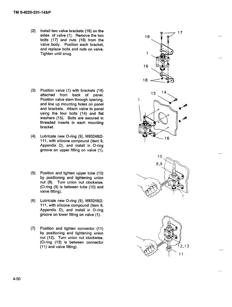
Install two valve brackets
(16) on the
17
sides
of valve (1). Remove the two
16
bolts (17) and nuts (18) from the
valve body.
Position each bracket,
and replace
bolts and nuts on valve.
Tighten until snug.
1
16
18
(3)
Position valve (1) with brackets
(16)
15
14
attached
from
back
of
panel.
Position valve stem through opening,
and line up mounting holes on panel
and brackets.
Attach valve to panel
using the four bolts (14) and flat
washers
(15).
Bolts are secured
in
threaded
inserts
in each mounting
bracket.
(4)
Lubricate new O-ring (9), M83248/2-
--16
111, with silicone compound
(Item 9,
Appendix
D), and install in O-ring
groove on upper fitting on valve (1).
10
8,9
(5)
Position and tighten upper tube (10)
by positioning
and tightening
union
nut (8). Turn union nut clockwise.
(O-ring (9) is between tube (10) and
valve fitting).
(6)
Lubricate new O-ring (9), M83248/2-
111, with silicone compound
(Item 9,
Appendix
D), and install in O-ring
groove on lower fitting on valve (1).
(7)
Position
and tighten connector
(11)
by positioning
and tightening
union
nut (12).
Turn union nut clockwise.
(O-ring (13) is between
connector
(11) and valve fitting).
12,13
@@l
6
4-50


