
TM 5-4220-211-12&P
APPENDIX B
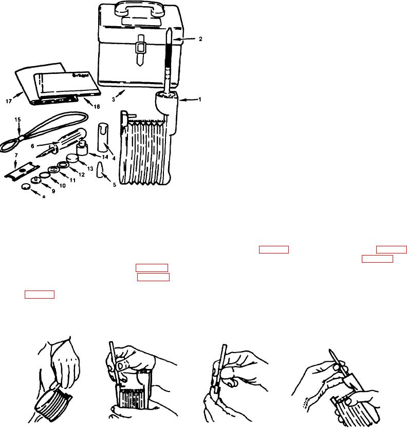
MULTI-GAS DETECTOR SET
1. Gas detector pump Model 31
2. DRAGER Tubes*
3. Carrying case
4. Break off husk
5. Rubber cap
6. Screwdriver
7. Special spanner
8. Filter sieve
9. Valve disc
10. Washer
11. Gasket
12. Rubber ring
13. Valve seat
14. Rubber bung
15. Carrying strap
16. Instructions for Use
17. Detector Tube Handbook
*The DRAGER Tubes are not supplied with the
instrument, but must be ordered separately as a function
of the gas type. See Prospectus 2341 e and Table
2340e).
Figure B-1. Multi Gas Detector
Section I
B-1. SUMMARY OF OPERATING INSTRUCTIONS.
a. Check the pump for leaks before each series of measurements.
b. Break off both tips of the DRAGER Tube in the break-off eyelet (Fig. B-3) or in the break-off husk (Fig. B-4).
c. Tightly insert the DRAGER Tube in the pump head with the arrow pointing towards the pump (Fig. B-5).
d. Hold the pump as shown in Fig. B-6.
e. Fully compress the bellows (Fig. B-7).
f.
Straighten the fingers. The suction process takes place automatically and is completed when the limit chain
is taut (Fig. B-9).
g. Repeat the suction process as often as specified in the Tube Operating Instructions.
h. Evaluate the indication as described in the Tube Operating Instructions.
Figure B-2.
Figure B-3.
Figure B-4.
Figure B-5.
Carrying Strap.
Breaking-Off Eyelet
Breaking-Off Husk
Inserting Tube in Pump Head
B-1