
TM 5-4220-211-12&P
Section IV
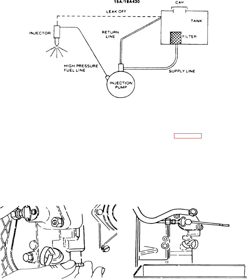
FUEL SYSTEM/GOVERNOR
Figure A-66. Gravity Feed - Automatic Bleed
A-5.
FUEL PROMER DEVICE.
a. Model 18A430 has a primer knob built into the crankcase below the injection pump. It operates much like the
lever already described, except it must be pulled downward to prime the engine. On all models, the speed control must be
full open before the primer device will engage. Model 15A430 has no priming device. (Figure A-67.)
b.
V-twin engines feature a fuel primer push button built into the injection pump; again , it works much like the
others.
A-6.
FUEL SYSTEM. Checking timing.
a.
Add one quart diesel fuel to engine.
b.
Set speed control lever to mid-range. Primer control (extra fuel button) not pulled.
c.
Locate and mark the timing marks on flywheel and engine housing.
Figure A-68. Fuel System
Figure A-67. Fuel Primer Device
A-24

