
TM 5-4220-211-12&P
15A430/18A430 DISASSEMBLY/ASSEMBLY
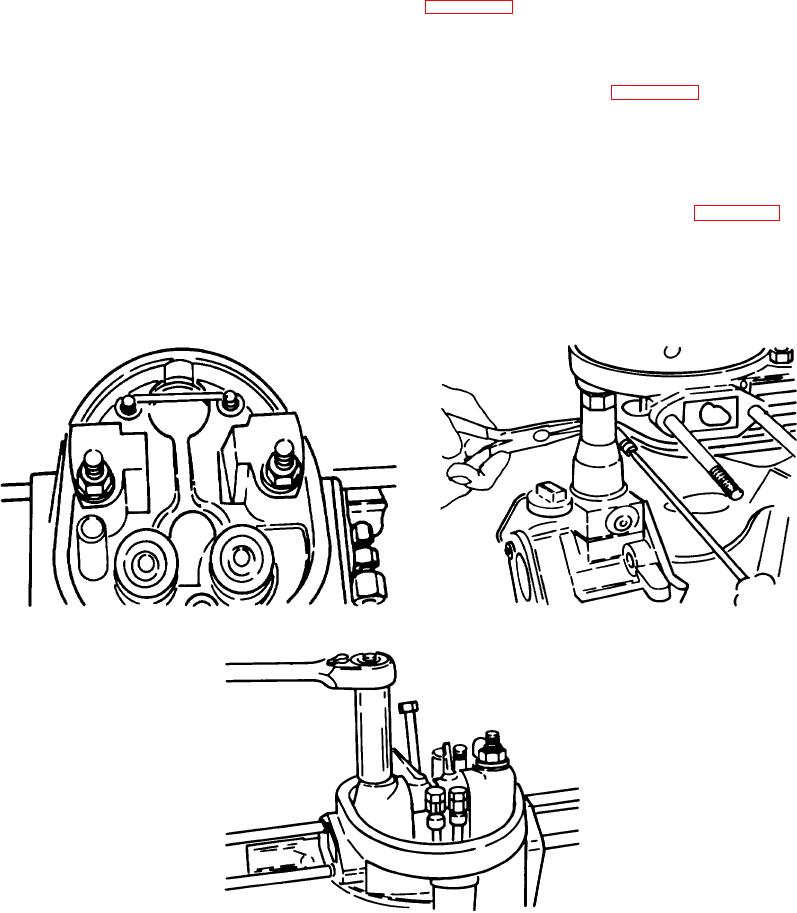
(1) Slide the push rod tube down onto the compression release. Install the push rod tube retaining spring in
the top of the cylinder head exactly as shown. (Figure A-58.)
(2) Insert the push rods through the push rod tube into the top of the compression release. Both push rods
are alike. The opening in the compression release closest to the engines center is for the intake push
rod. This rod should go to the rocker arm on the air cleaner (intake) side of the engine. Install the
cylinder shield bolt and tighten using a screwdriver and needlenose pliers. (Figure A-59.)
q. Rocker Arms. Run the flywheel counterclockwise until the compression stroke is reached. Install the rocker
arms by placing them into the cylinder head and tapping in the rocker arm shaft. Place each rocker arm over the proper
push rod as explained in step p. Oil the rocker arm shaft before installing.
(1) Torque the cylinder head, using a 13mm deep well socket, to the torque specified. After torquing,
tighten down the nuts holding the push rod tube retaining spring and adjust the valves. (Figure A-60.).
r.
Valve Adjustment. Be certain that the compression release mechanism is at the 9 o'clock position.
(1) This is the run position; the valves are not put into the compression release mode. Turn the flywheel
counterclockwise until one valve is open as wide as possible. With a 11mm open end wrench, loosen
the
Figure A-58. Push Rod Tube
Figure A-59. Plush Rod
Figure A-60. Rocker Arms
A-21

