
TM 5-4220-211-12&P
15A430/18A430 DISASSEMBLY/ASSEMBLY
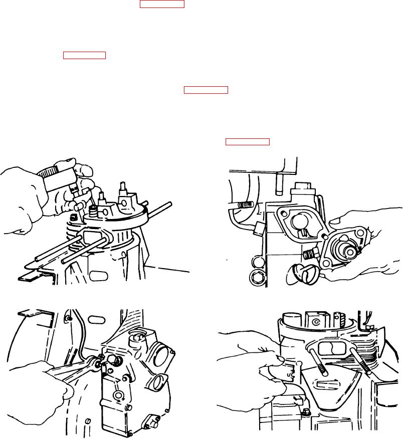
m. Fuel Injector. Replace the asbestos washer located in the cylinder head on the seating surface for the fuel
injector holder. Never place a new gasket on top of the old. Install the fuel injector and injector clamp. Torque the two
injector clamp nuts to engine specification. (Figure A-54.)
n. Injection Pump. Place the speed control lever in an approximately horizontal position. Set the injection
pump rack to the midpoint of its travel. These steps will insure that the injector rack pin mates properly with the governor
arm. Do not move the speed control lever before tightening down the injection pump. Install the same number and types
of shims and gasket as were on the engine when disassembled. (See Fuel/Governing System for complete injection
timing information.) (Figure A-55.)
o. High Pressure Fuel Line. Replace the pressure fuel line between the fuel injection pump and fuel injector.
Tighten the tube nut at the fuel injector using a 17mm open end wrench; tighten the two nuts at the injection pump using a
17mm flare nut wrench and a 14mm open end wrench. (Figure A-56.)
p. Push Rods. Push Rod Tube and Compression Release. Install the compression release and a new
gasket with a 4mm allen head.
Slide the push rod tube up into its hold in the cylinder head. Remember to install a new push rod tube o-ring on
the top of the compression release and the top of the push rod tube. (Figure A-57.)
Figure A-55. Injection Pump
Figure A-54. Fuel Injector
Figure A-57. Push Rods. Push Rod Tube and
Figure A-56 High Pressure Fuel Line
Compression Release
A-20

