TM 5-4220-231-14&P
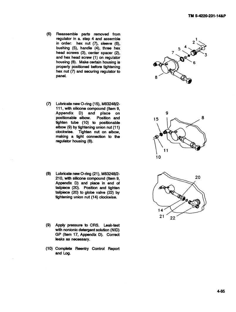
(6)
Reassemble
parts
removed
from
regulator
in a. stop 4 and assemble
in order
hex nut (7), sleeve
(6),
2
bushing
(5), handle
(4), three
hex
5
head
screws
(3), center
spacer
(2),
7
3
and hex head screw
(1) on regulator
housing
(8).
Make certain housing
is
6
properly
positioned
before
tightening
hex nut (7) and securing
regulator to
panel.
8
(7)
Lubricate now O-ring (15), M83248/2-
111, with silicone compound
(Item 9,
Appendix
D)
and
place
on
9
positionable
elbow.
Position
and
15
8
tighten
tube
(10)
to
positionable
elbow (9) by tightening
union nut (11)
clockwise.
Tighten
nut on elbow,
making
a tight connection
to the
regulator
housing
(8).
10
(8)
Lubricate
new O-ring (21), M8324812-
210, with silicone compound
(Item 9,
20
Appendix
D) and place
in end of
tailpiece
(20).
Position
and tighten
tailpiece
(20) to globe valve (22) by
tightening
union nut (14) clockwise.
14
21
22
(9)
Apply pressure
to CRS.
Leak-test
with nonionle detergent
solution
(NID)
GP (Item 17, Appendix
D). Correct
leaks as necessary.
(10) Complete
Reentry
Control
Report
and Log.
20
1@4
4-86