
TM 5-4220-211-12&P
Section V
LUBRICATION/COOLING SYSTEM
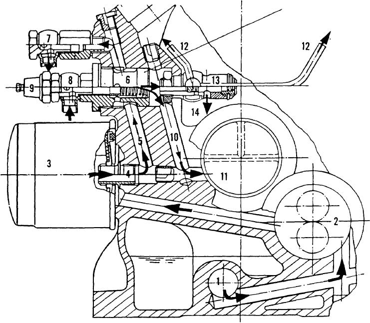
A-11. LUBRICATION SYSTEM OPERATION (2 CYLINDER ENGINE). Engine oil is drawn through the oil strainer (1)
by the oil pump) (2) and pushed upwards towards the spin-on oil filter (3). The filtered oil flows through the filter adapter
connector (4) into the crankcase oil duct (5). Oil flows up the crankcase oil duct and around the relief valve (6), leaving th e
crankcase at banjo connector (7) to pass through the external oil cooler (not shown). If the oil cooler becomes clogged,
relief valve (6) will open, discharging the oil directly into oil duct (10) and towards spray tube (12). If the cooler is clear, oil
re-enters the engine through banjo union (8), passes through the relief valve, through oil duct (10) and lubricates the
crankshaft main bearing. A smaller quantity of oil goes from the relief valve (6) into two spray tubes (12) which lubricate
the valve gear. Oil drains through return passages to the oil pan, completing the lubrication circuit.
If oil pressure becomes too high, however, main relief valve (13) discharges the oil directly back into the oil pan
through passage (14). Oil pressure switch (9) opens the main relief valve when it senses high oil pressure. Figure A-73.
Figure A-73. Lubrication System Operation (2 Cylinder Engine)
A-29