
TM 5-4220-211-12&P
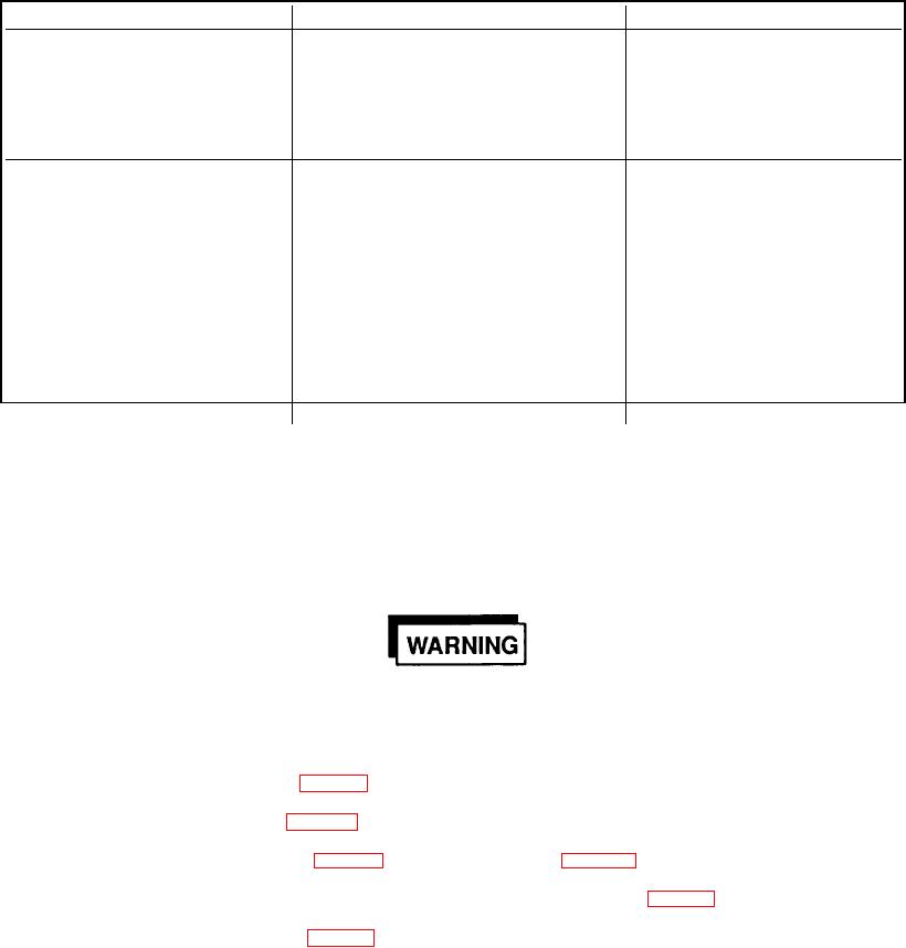
Table 4-4. ENGINE TROUBLESHOOTING (con't)
Symptom
Probable Cause
Correction
Excessive Oil Consumption
Piston Rings Worn or Sticking,
Inspect and Free Rings or
Cylinder
Overhaul Engine
Wall(s) Scuffed or Scratched
Oil Leaking
Inspect and Tighten Fittings as
Needed
Unusual Engine Knocks
Loose Mounting Bolts
Inspect and Tighten
and Noises
Any Loose Bolts
Engine Overload
Reduce Engine Load
Loose Flywheel
Tighten Flywheel Mounting Bolts
Damaged Gear Teeth
Replace Any Gear with Broken
Teeth; Also Examine Gear it
Engages for Damage
Incorrect Timing
Correct Injection Pump Timing
NOTE
This table is not intended to cover every possible symptom, but is rather a list of the more
frequent problems and some of their causes.
Section V
REMOVAL OF MAJOR ASSEMBLIES
4-8.
COMPRESSOR. The compressor may be removed from the frame as follows:
Compressor piping may contain high pressure. Never attempt to service or repair any
portion of the compressor until all pressure has been released to the atmosphere.
a.
Remove drive belt. (Ref. para 4-4g).
b.
Disconnect gauge lines (40, Fig. 4-2).
c.
Remove gauge panel (22, Fig. D-2).
d.
Disconnect discharge hose (30, Fig. D-2) at the final separator (Fig. D-12).
e.
Remove 4 bolts, 4 nuts, 4 lock washers and 12 flatwashers (45, 46, 47, 48, Fig. D-2).
f.
Move compressor assembly (1, Fig. D-2) straight out through beltguard side of the frame and place on a flat,
level surface.
4-15