CHAPTER 22 — Recompression Chamber Operation
Change A 22-9
22-2.5.3
Pressure Gauges. Chambers must be fitted with appropriate pressure gauges.
These gauges, marked to read in feet of seawater (fsw), must be calibrated or
compared as described in the applicable Planned Maintenance System (PMS) to
ensure accuracy in accordance with the instructions in Chapter 4.
22-2.5.4
Relief Valves. Recompression chambers should be equipped with pressure relief
valves in each manned lock. Chambers that do not have latches (dogs) on the
doors are not required to have a relief valve on the outer lock. The relief valves
shall be set in accordance with PMS. In addition, all chambers shall be equipped
with a gag valve, located between the chamber pressure hull and each relief valve.
This gag valve shall be a quick acting, ball-type valve, sized to be compatible with
the relief valve and its supply piping. The gag valve shall be safety wired in the
open position
22-2.5.5
Communications System. Chamber communications are provided through a
diver’s intercommunication system, with the dual microphone/speaker unit in the
chamber and the surface unit outside. The communication system should be
arranged so that personnel inside the chamber need not interrupt their activities to
operate the system. The backup communications system may be provided by a set
of standard sound-powered telephones. The press-to-talk button on the set inside
the chamber can be taped down, thus keeping the circuit open.
22-2.5.6
Lighting Fixtures. Consideration should be given to installation of a low-level
lighting fixture (on a separate circuit), which can be used to relieve the patient of
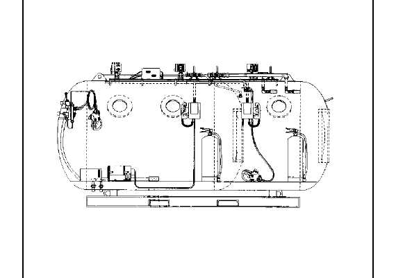
Figure 22-9. Fly Away Recompression Chamber.