TM 5-4220-231-14&P
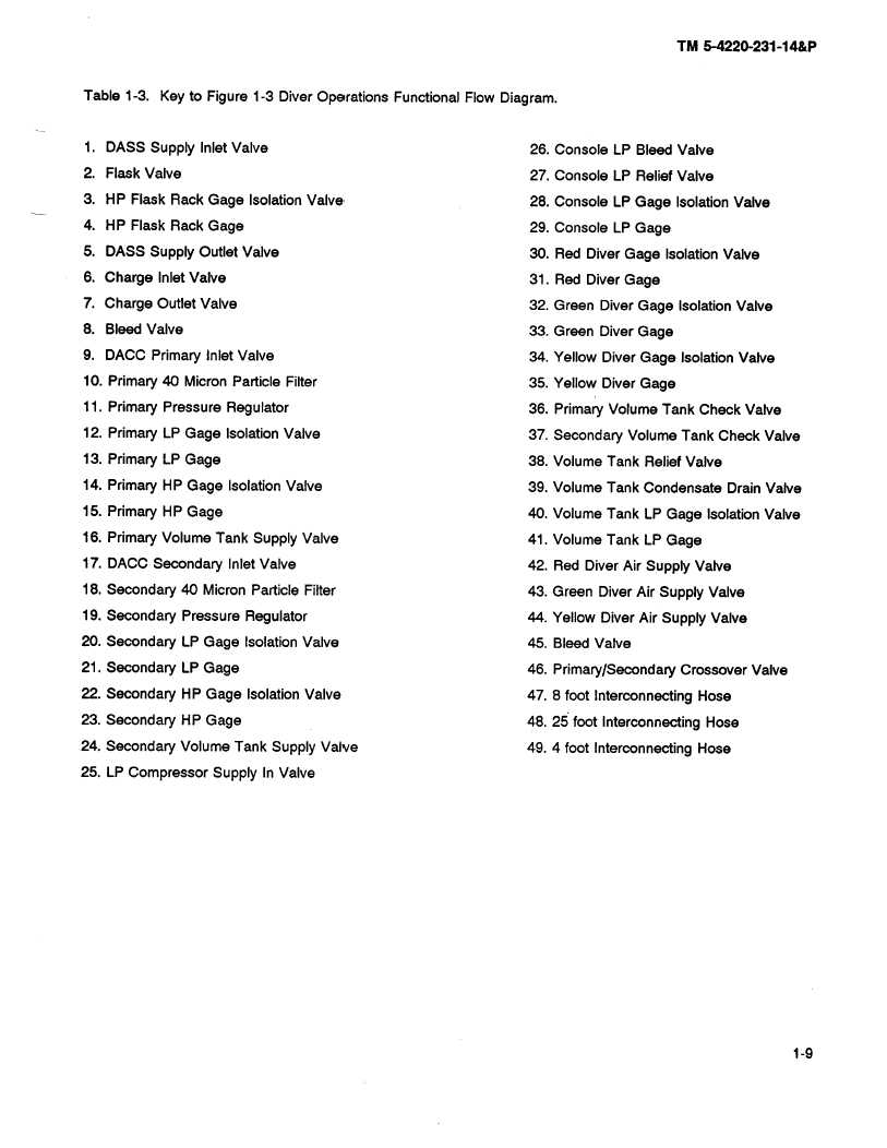
Table1-3.
Key to Figure 1-3 Diver Operations Functional Flow Diagram.
1. DASS Supply Inlet Valve
26. Console
LP Bleed Valve
2.
Flask Valve
27. Console
LP Relief Valve
3.
HP Flask Rack Gage
Isolation Valve
28. Console
LP Gage
Isolation Valve
4.
HP Flask Rack Gage
29. Console
LP Gage
5.
DASS Supply Outlet Valve
30. Red Diver Gage
Isolation Valve
6.
Charge
Inlet Valve
31. Red Diver Gage
7.
Charge
Outlet Valve
32. Green
Diver Gage
Isolation Valve
8.
Bleed Valve
33. Green
Diver Gage
9.
DACC Primary
Inlet Valve
34. Yellow Diver Gage
Isolation
Valve
10.
Primary 40 Micron Particle
Filter
35. Yellow Diver Gage
11.
Primary
Pressure
Regulator
36. Primary Volume Tank Check Valve
12.
Primary LP Gage
Isolation Valve
37. Secondary
Volume Tank Check Valve
13. Primary
LP Gage
38. Volume Tank Relief Valve
14. Primary
HP Gage
Isolation Valve
39. Volume Tank Condensate
Drain Valve
15. Primary
HP Gage
40. Volume Tank LP Gage
Isolation Valve
16. Primary Volume Tank Supply Valve
41. Volume Tank LP Gage
17. DACC Secondary
Inlet Valve
42. Red Diver Air Supply
Valve
18. Secondary
40 Micron Particle
Filter
43. Green
Diver Air Supply
Valve
19. Secondary
Pressure
Regulator
44. Yellow Diver Air Supply
Valve
20. Secondary
LP Gage
Isolation Valve
45. Bleed Valve
21. Secondary
LP Gage
46. Primary/Secondary
Crossover
Valve
22. Secondary
HP Gage
Isolation
Valve
47. 8 foot Interconnecting
Hose
23. Secondary
HP Gage
48. 25 foot Interconnecting
Hose
24. Secondary
Volume Tank Supply
Valve
49. 4 foot Interconnecting
Hose
25. LP Compressor
Supply
In Valve


