TM 5-4220-231-14&P
(3)
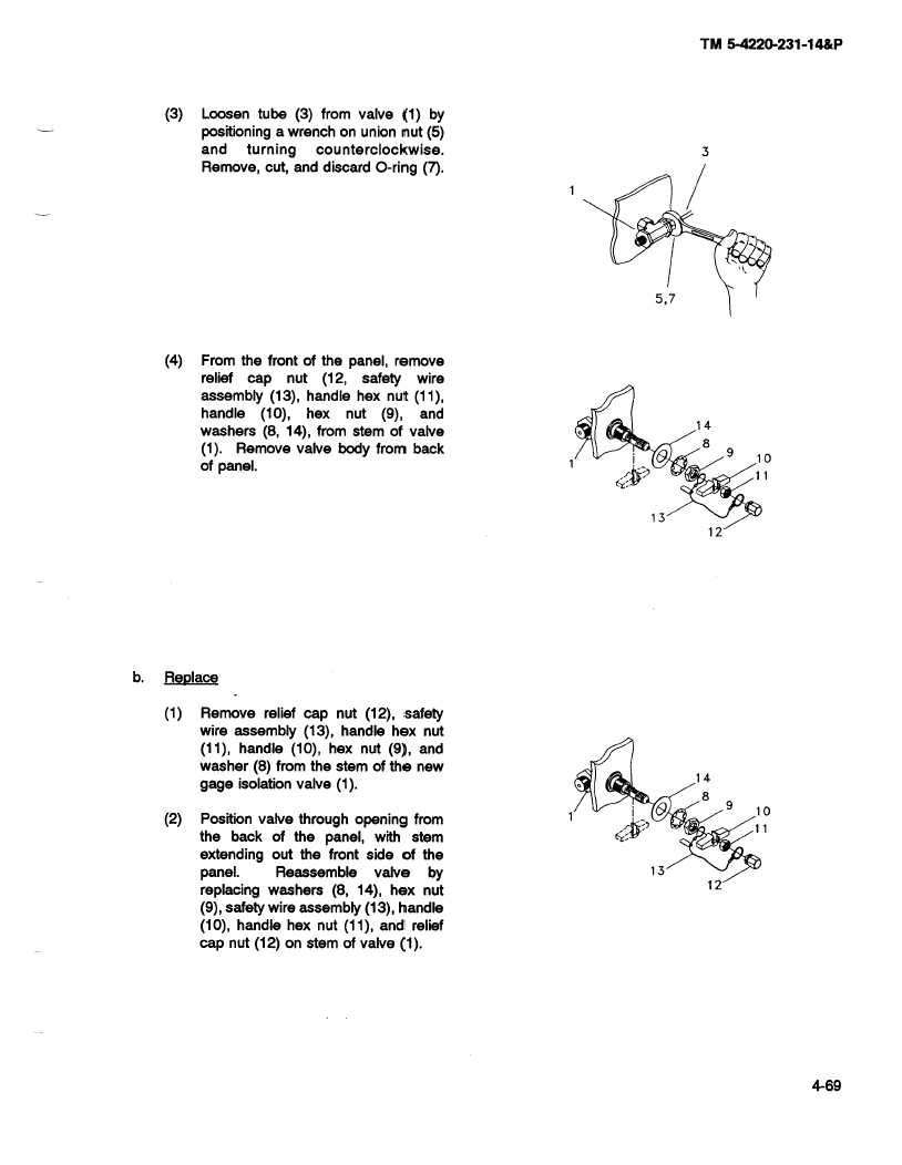
Loosen tube (3) from valve (1) by
positioning a wrench on union nut (5)
and
turning
counterclockwise.
3
Remove,
cut, and discard O-ring (7).
5,7
(4)
From the front of the panel, remove
relief cap
nut (12, safety
wire
assembly
(13), handle hex nut (11),
handle
(10), hex
nut (9), and
14
washers
(8, 14), from stem of valve
(1). Remove valve body from back
9
10
of panel.
13
12
b.
Replace
(1)
Remove relief cap nut (12), safety
wire assembly
(13), handle hex nut
(11), handle (10), hex nut (9), and
washer (8) from the stem of the new
14
gage isolation valve (1).
8
(2)
Position valve through
opening
from
9
10
the back of the panel, with stem
extending
out the front side of the
panel.
Reassemble
valve
by
13
12
replacing
washers
(8, 14), hex nut
(9), safety wire assembly
(13), handle
(10), handle hex nut (11), and relief
cap nut (12) on stem of valve (1).
@5
4-69

