
TM 5-4220-211-12&P
Section II
B-2. DESCRIPTION OF THE INSTRUMENT.
The two essential components of the DRAGER Multi Gas Detector are the gas detector pump (also called the bellows
pump) and DRAGER Tubes chosen as a function of the measurement to be carried out. The pump and Tube together
form a complete unit. All the information given in DRAGER publication on the reliability of the indications as valid
only when a DRAGER bellows pump is used in conjunction with DRAGER Tubes.
The DRAGER Multi Gas Detector Model 21/31 (Fig. B-l) consists of a carrying case containing the bellows pump Model
31, a carrying strap, a break-off husk, tools and spare parts for maintenance of the pump, the Instructions for Use, the
Detector Tube Handbook and a supply of rubber caps for sealing used detector tubes. The case also has space for a
supply of detector tubes and various accessories.
The bellows pump simultaneously sucks in and measures the gas volume. It has been designed for maximum simplicity
and accuracy. The pump can easily be operated with one hand and sucks in 100 cm3 per stroke.
The pump can be carried around the wrist by means of a carrying strap (Fig. B-2).
Section III
B-3. USE OF THE INSTRUMENT.
a. Breaking-off the tips of the Tube. Break off both tips of the DRAGER Tube in the break-off eyelet (Fig. B-3). The break
off husk (Fig. B-4) can also be used for this purpose. This ensures that glass splinters do not fall onto the floor.
b. Inserting the DRAGER Tube in the Pump. Insert the opened DRAGER Tube in the pump head so that the arrow points
towards the pump. The Tube must fit firmly and tightly in the pump head stopper so that no by-pass air can be sucked in
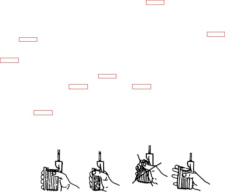
c. Sucking-in the Gas Sample. Hold the pump in the hand with the pump between the thumb and the base of the index
finger and the fingers resting on the front plate. (Fig. B-6).
Compress the bellows completely (Fig. B-7) and then release it (Fig. B-9). When the bellows is compressed, the air in it
escapes through the outlet valve and not through the Tube, since the Tube has a much higher resistance than the outlet
valve. The pump suction operation commences when the fingers are relaxed. The compression springs inside the
bellows, which are placed under stress when the bellows is compressed, extend and the outlet valve is closed through the
vacuum created in the bellows. The air flows through the DRAGER Tube into the bellows while the latter returns to its
original volume (Fig. B-4). The volume of air sucked-in by the DRAGER Tube is defined by the dimensions and stroke of
the bellows. It amounts to 100 cm3 per stroke. The end of the suction movement is reached when the limit chain is
completely taut. Since the suction of the pump is caused only by the relaxation of the springs, any subjective influence is
excluded.
Figure B-6.
Figure B-7.
Figure B-8. Compressing
Figure B-9. Tauting
Pump
Compressing Bellows
Bellows Incorrectly
of Limit Chain
B-2

