
TM 5-4220-211-12&P
15A430/18A430 DISASSEMBLY/ASSEMBLY
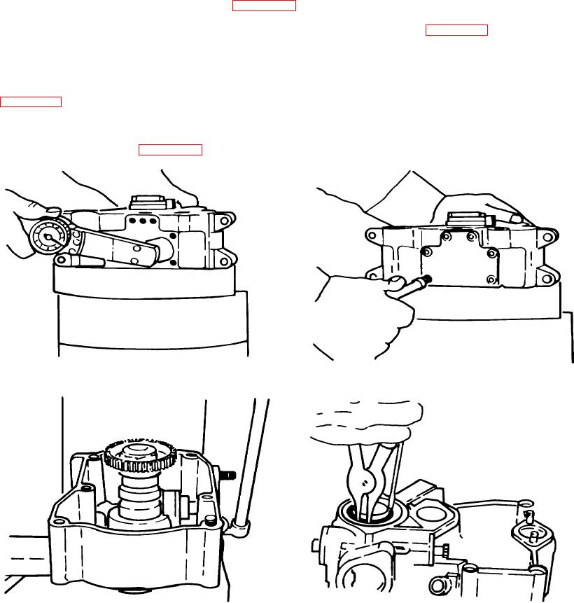
(1) Install connecting rod into the crankcase until it seats on the crankshaft. Insert the connecting rod cap
through the inspection cover. Torque the connecting rod nuts to 22ft. lbs. Use new nuts whenever the
connecting rod cap is removed. (Figure A-37.)
(2) With a 4mm allen head wrench, reinstall the crankcase inspection cover. (Figure A-38).
f.
Camshaft. Using the driver supplied in the special tools set, press the camshaft bearing into the gear cover.
Now press the camshaft into the camshaft bearing; again, use the appropriate special tool. Turn the gear cover
over and check the camshaft bearing. It should be completely seated against the gear cover bearing flange.
(1) Replace the nylon o-ring retainer on the end of the camshaft bearing so that its shoulder faces out.
Press the o-ring into the retainer. Next, using a snap ring pliers, replace the bearing retaining ring in the
gear cover. (Figure A-40.)
Figure A-37. Installation of Connecting Rod
Figure A-38. Reassembly of Crankcase Cover
Figure A-39. Camshaft
Figure A-40. Replacing nylon o-ring
A-15

